HLS Swing Door Multipoint Hardware Installation and Adjustment
This guide provided by All About Doors & Windows (www.allaboutdoors.com) pertains specifically to HOPPE HLS multipoint swing doors and their hardware. Included in this article are instructions on installing hardware, dealing with possible operation issues, adjusting the hardware and assembling the inactive gear.
Installation of Multipoint Swing Door Hardware
- 1) Position your lockcase as though you were about to insert it into the door. Make sure the bevel is going the right direction. It should be facing in a direction such that when the door closes, the bevel allows the door to clear the edge of the door frame and the latch is able to slide into the strikeplate in the doorframe, thereby “stopping” the door in the frame. If the bevel is facing the wrong direction, the door will not be able to clear the edge of the frame at all.
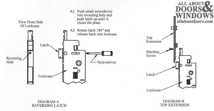
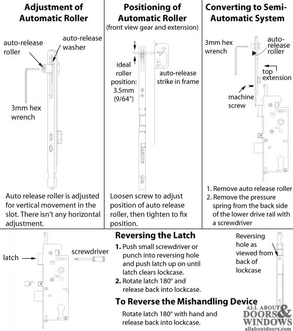
- Note: If you need to reverse the latch, push a small screwdriver or punch into reversing hole and push latch up until latch clears lockcase. Rotate latch 180° and release back into lockcase. (See Diagram A)
- 2) Slide main gear into mortised space in door, aligning holes drilled in door face with the cylinder, handle holes and lockcase to properly accommodate trim.
- 3) Install handle set per your specific swinging patio door handle set installation instructions.
- 4) Remove machine screw in top of lockcase. Slide top extension into place and fasten to lockcase with the supplied machine screws (See Diagram B) to door edge. Use #6 screws. The #6 screws should be installed flush with the faceplate, but not over-tightened.
- 5) Test gear with the door in the open position. If your multipoint system does not operate on the edge of the door, engage system by lifting the handle, and extend the deadbolt by turning the thumbturn. If the system operates on the door edge, being able to operate the deadbolt will ensure that the hardware system is fully functional.
- Note: Main gear and extensions should be hand-tightened only. Excessive force may cause drive rail to bind and inhibit system operation.
HOPPE HLS Multipoint Swing Door Troubleshooting Guide
| Problem | Probable Cause | Solution |
| System operates in the open position when I lift the handle, but not in the closed position with the door shut. | Improper installation of handle set. | Remove handle and reinstall. |
| System operates in the open position when I lift the handle, but not in the closed position with the door shut. | Improper placement of door in frame | Check to make sure the door is square in the frame |
| Locking points will not engage with the door shut. | If automatic version, the auto release pin may not be adjusted properly. | Adjust the hardware (instructions below) |
HLS9000 Hardware Adjustment
Inactive Assembly Instructions
We recommend assembly of the inactive gear in the activated (locked) position. This will keep your door closed most of the time but allow you to retract the shootbolts to open it if desired.

To install the gear:
- 1) Align the main gear body within the mortise. If you're using a jig to center the gear on the handle hole, slide the gear body into place and screw it down. If you're not using a jig, align the gear with the panel bottom. If your lock is a 3-piece, extend the shootbolts of the bottom extension and set the extension in place along the door. Line up the main gear body with the bottom extension and mark your installation point from there. Screw in place.
- 2) Operate and extend the shootbolt mechanism on the main gear body with the handle. Then lock the thumbturn mechanism (cylinder). The thumbturn will spin freely after it hits the locking point. If the thumburn mechanism feels as though it has hit the locking point but does not spin freely, the mechanism is not working properly.
- 3) If your lock is a 3-piece, connect the drive rail of the bottom extension to the connector of the main gear. Make sure the teeth are fully engaged (seated in the connector). The shootbolts should extend ¾” or 1” (model options). Screw the bottom extension to the stile (the vertical inside edge of the door).
- 4) Connect the drive rail of the top extension to the connector of the main gear. Make sure the teeth are fully engaged with the main lock, and screw the top extension to the stile (vertical inside edge of the door). The shootbolts should extend 3/4" or 1". Note: The system is tolerant; there is an allowance of up to 1/8” (3mm) between the gear and extensions.
- 5) Finish screwing the inactive system onto the stile. Be sure you install screws in the holes that will not be filled when the astragal is applied.
- 6) Unlock the thumbturn mechanism. Operate the handle to retract and extend the shootbolts. The shootbolt mechanisms should operate freely.
- 7) Now try to operate the shootbolts while the lock is engaged. The shootbolts should not retract.